
Important Installation Information
Installation Instructions to Ensure your Guarantee
Deck installation instructions
Important Installation Requirement
PLEASE ENSURE THAT THE Following is adhered to in order to make sure that your GUARANTEE IS IN PLACE.
THE SPACING BETWEEN THE JOISTS on a residential deck must be 350mm from the center of the joist to the center of the next joist. On a commercial or public deck installation this must be reduced to 300mm.THE CLOSER THE BETTER in all cases. The increase in the strength of the deck plank increases dramatically for every 10mm narrower it is supported.
YOU HAVE TO USE THE CLIPS everywhere you CANNOT PUT SCREWS THROUGH THE DECK PLANKS THAT IS THE REASON FOR HAVING THE CLIPS.
LAYING THE PLANKS AND UNDERSTANDING WHAT TO DO WHEN YOU HAVE TO BUTT PLANKS TOGETHER.
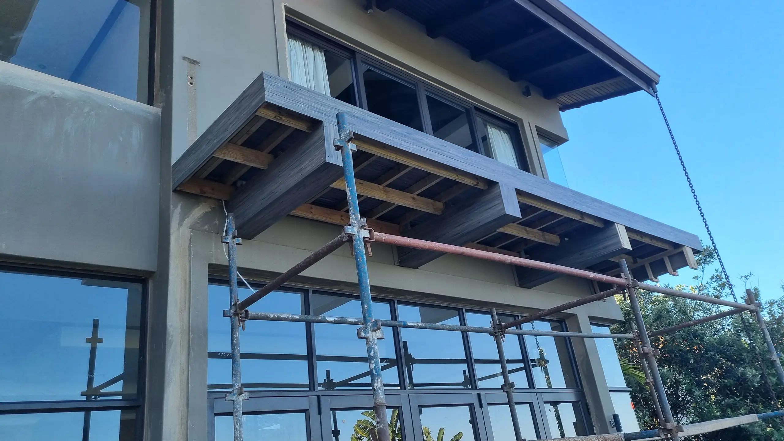
You have to MAKE SURE that every plank irrespective of how short it is or how long it is uses a full clip at the beginning of a plank and at the end of a plank. The ends of a plank HAVE TO SIT ON THE SUPPORT STRUCTURE THEY CANNOT BE FLOATING.
Planks have to be supported with a batten or beam they cannot be straight onto a surface.
The Support Structure
THIS IS THE MOST IMPORTANT REQUIREMENT Your support beams all HAVE TO BE AT THE EXACT SAME LEVEL (THEY CAN NOT VARY IN HEIGHT AT ALL), this allows the plank to expand and contract on a FLAT LEVEL SURFACE, as opposed to a WAVED TYPE SURFACE (WHICH PUTS PRESSURE ON THE PLANKS. PRESSURE ON THE PLANKS IS UNACCEPTABLE when it comes to COMPOSITE WOOD DECK PLANKS they do not want to be put under any pressure and must be allowed to move freely. (THIS ALSO MEANS DON’T OVER TIGHTEN THE SCREWS. The DECK STRUCTURE HAS TO BE SOUND AND SOLID there can be no movement in your structure the structure must feel like a concrete slab (that is how solid it needs to be). Failed decking 9.9 times out of 10 is due to a failed deck structure. REMEMBER STRUCTURE IS JUST ANOTHER WORD FOR FOUNDATION, YOU CANT BUILD ON A BAD FOUNDATION.
EXPANSION AND CONTRACTION
MAKE SURE you allow for those EXPANSION AND CONTRACTION gaps. One can make the inner gaps slightly smaller PROVIDED U HAVE INCREASED THE EXPANSION GAPS ON THE ENDS but even if you do this you must still have small expansion gaps between the planks that are butted up against each other.NO NAILS OR SCREWS ARE TO BE USED THROUGH THE PLANKS, as this could lead to splitting of the deck planks. The MAXIMUM SPAN WIDTH is 350mm center-to center.
Expansion and Contraction
MAKE SURE you allow for those EXPANSION AND CONTRACTION gaps. One can make the inner gaps slightly smaller PROVIDED U HAVE INCREASED THE EXPANSION GAPS ON THE ENDS but even if you do this you must still have small expansion gaps between the planks that are butted up against each other.NO NAILS OR SCREWS ARE TO BE USED THROUGH THE PLANKS, as this could lead to splitting of the deck planks. The MAXIMUM SPAN WIDTH is 350mm center-to center.
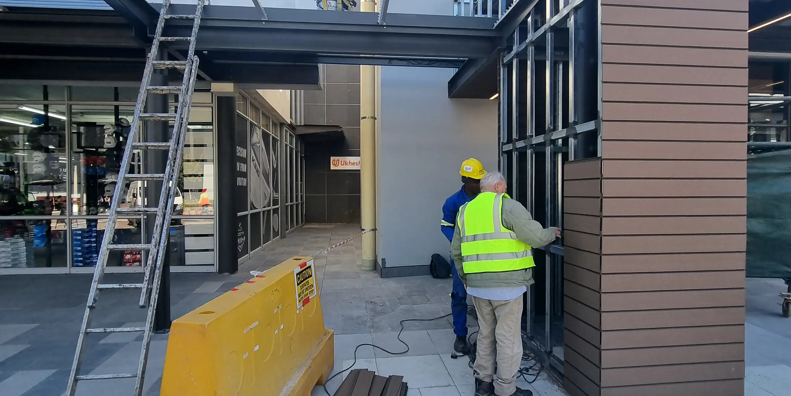
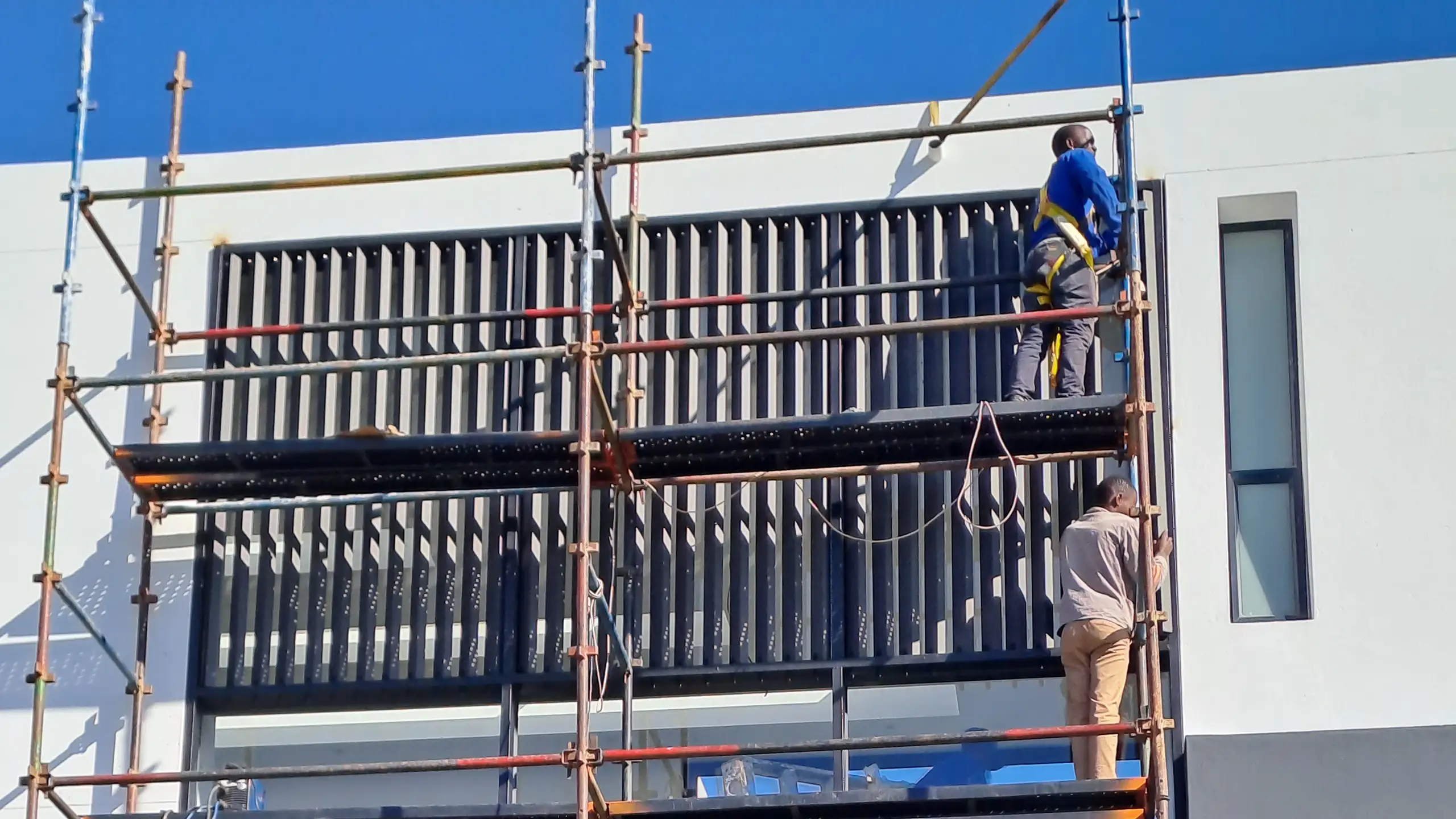
Fitting the Fascia
The Facia can be screwed into the structure using a flat head screw which you do not countersink into the material. PRE- DRILLED you also need to slot the hole from left to right to make it slightly wider than the shaft of the screw without over tightening it this will allow for any expansion and contraction.
Installation as Easy as 1, 2, 3
All our composite wood products can be machined using normal woodworking tools.
At Best Deck, our products are installed using a specially-designed Best Deck solid plastic clip, which allows for movement and also aids in record time installation.
Decking Structure: Foundation
The installation and initial structure of the deck is the most important aspect of achieving the results you desire. And at Best Deck, we do everything we can to facilitate the installation process.
There are multiple options for the structure of a deck, and we suggest you either contact one of our Sales Directors or call us of you have any queries.
Earth, Gravel or Soil Installation
01

02

03

04

Digging the hole to insert the frrame structure
The size of the hole should be approximately 600×600, the depth of the hole increases based on how high the deck is above ground level. the diagram shows suggested depths based on the height (100mm – 2.5m off the ground) A,B & C are suggested depths. (subject to change due to conditions)
05

Building the support footings
Build a T-piece anchor as per drawing 2. This is done with the galvanised steel you are using for the entire frame work. Drawing 2 shows the minimum requirements for this application, as the deck gets higher, it increases the length of the T-piece anchor as well as you would add more T-pieces to the vertical support as the deck becomes higher off the ground as per the diagram.
06

Insert the welded T-piece
Insert the welded T-piece into the hole at the suggested depth as shown in figure 3. The deeper the hole, the more T-pieces are required. Its always a good idea to add more supports that can be welded in at various angles to create a stronger support.
07

Fill up the hole with concrete
Securing the T-piece and ensuring it is 100% vertical as shown in the drawing. It is always a good idea to allow the vertical footing to be left longer than required for easy installation of the deck base, as well as allow the cement to cure correctly.
08

Vertical footings for grid layout
The support footings must be spaced out at a maximum of 1 metre apart as shown in the diagram. In order for grass to stop growing through the deck you can use bidem cloth below the deck to kill light on the grass, or use grass poison.
09
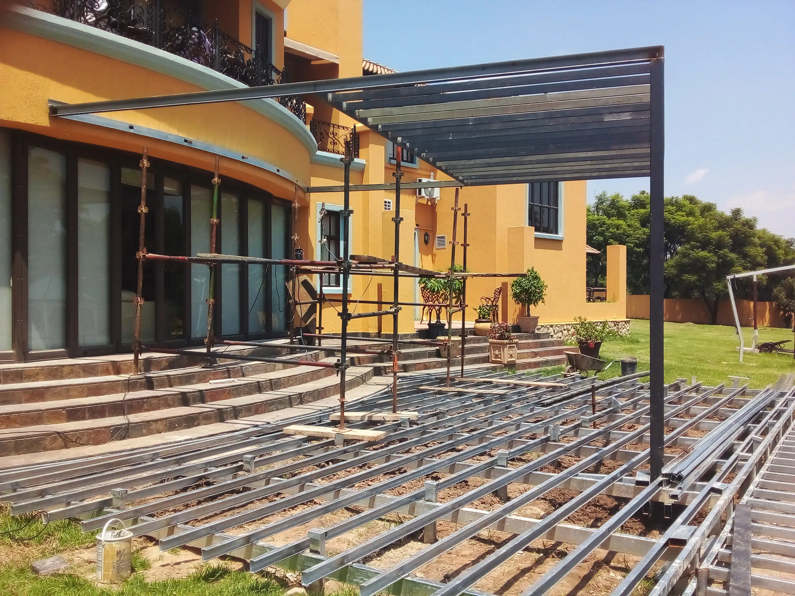
Welding bearer supports
Weld lipped channel beams to the vertical footings at a distance specified (not wider than 1 metere apart), these bearers will be the support for the joisting to create the grid to which the deck planks will be fitted.
10

Building the support joist grid
Running in the opposite direction to your support bearers, one adds the joists. Importantly, on a residential installation 350mm spacing between joists and on a commercial installation, 300mm spacing between joists are also the light weight c-channel, supplied by Best Deck. Ensure all welds are secure and primed.
11

Lay your decking planks
Lay your decking planks to your secure, rigid joists using the supplied Best Deck clip and screw.
